- 您现在的位置:买卖IC网 > Sheet目录484 > NOIL1SC4000A-GDC (ON Semiconductor)IC IMAGE SENSOR 4MP 127-PGA
NOIL1SM4000A
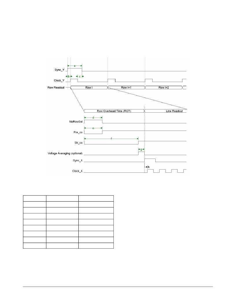
X and Y Addressing
To read out a frame, the lines are selected sequentially.
Figure 16 gives the timing to select the lines sequentially.
This is done with a Clock_y and Sync_y signal. The Sync_y
signals synchronizes the y-addressing and initializes the
y-address selection registers. The start address is the address
downloaded in the SPI multiplied by two.
On the rising edge of Clock_y the next line is selected. The
Sync_y signal is dominant and from the moment it occurs,
the y-address registers are initialized. If a Sync_y pulse is
given before the end of the frame is reached, only a part of
the frame is read. To obtain a correct initialization, Sync_y
must contain at least one rising edge of Clock_y when it is
active.
Figure 16. X and Y Addressing
Table 7. READOUT TIMING SPECIFICATIONS
Symbol Name Value
time to get the data stable from the pixels to the output bus
before the output stages. This ROT is in fact lost time and
rather critical in a high-speed sensor. Different timings to
a
b
c
d
e
f
g
h
Sync_Y
Sync_Y ? Clock_Y
Clock_Y ? Sync_Y
NoRowSel
Pre_col
Sh_col
Voltage averaging
Sync_X ? Clock_X
> 20 ns
> 0 ns
> 0 ns
> 50 ns
> 50 ns
200 ns
> 20 ns
> 0 ns
reduce this ROT are explained later in this section.
During the selection of one line, 2048 pixels are selected.
These 2048 pixels must be read out by one (or two) output
amplifier.
The pixel rate is the double frequency of the Clock_x
frequency. To obtain a pixel rate of 66 MHz, apply a pixel
clock Clock_x of 33MHz. When only one analog output is
used, two pixels are output every Clock_x period. When
Clock_x is high, the first pixel is selected; when Clock_x is
low, the next pixel is selected. Consequently, during one
As soon as a new line is selected, it must be read out by the
output amplifiers. Before the pixels of the selected line can
be multiplexed onto the output amplifiers, wait for a certain
time, indicated as the ROT shown in Figure 16. This is the
complete period of Clock_x two pixels are read out by the
output amplifier.
If two analog outputs are used each Clock-X period one
pixel is presented at each output.
http://onsemi.com
15
发布紧急采购,3分钟左右您将得到回复。
相关PDF资料
NOIL1SE3000A-GDC
IC IMAGE SENSOR 3MP 369-PGA
NOIL1SM0300A-WWC
IC IMAGE SENSOR LUPA300 48LLC
NOIL2SC1300A-GDC
IC IMAGE SENSOR LUPA1300 168PGA
NOIV1SE025KA-GDC
IC IMAGE SENSOR 25MP 355PGA
NP100P04PDG-E1-AY
MOSFET P-CH -40V MP-25ZP/TO-263
NP100P04PLG-E1-AY
MOSFET P-CH -40V MP-25ZP/TO-263
NP100P06PDG-E1-AY
MOSFET P-CH -60V MP-25ZP/TO-263
NP100P06PLG-E1-AY
MOSFET P-CH -60V MP-25ZP/TO-263
相关代理商/技术参数
NOIL1SE0300A-QDC
功能描述:SENSOR IMAGE COLOR CMOS 48-LCC RoHS:否 类别:传感器,转换器 >> 图像,相机 系列:- 标准包装:480 系列:- 象素大小:6.7µm x 6.7µm 有源象素阵列:768H x 488V 每秒帧数:52 电源电压:3.3V 类型:CMOS 成像 封装/外壳:48-QFP 供应商设备封装:48-QFP 包装:托盘 请注意:* 配用:4H2105-ND - HEADBOARD FOR KAC-004014H2104-ND - KIT EVAL FOR KAC-00401 其它名称:4H20954H2095-NDKAC-00401-CBC-LB-A0
NOIL1SE3000A-GDC
功能描述:IC IMAGE SENSOR 3MP 369-PGA RoHS:是 类别:传感器,转换器 >> 图像,相机 系列:* 标准包装:480 系列:- 象素大小:6.7µm x 6.7µm 有源象素阵列:768H x 488V 每秒帧数:52 电源电压:3.3V 类型:CMOS 成像 封装/外壳:48-QFP 供应商设备封装:48-QFP 包装:托盘 请注意:* 配用:4H2105-ND - HEADBOARD FOR KAC-004014H2104-ND - KIT EVAL FOR KAC-00401 其它名称:4H20954H2095-NDKAC-00401-CBC-LB-A0
NOIL1SM0300A-QDC
功能描述:IC IMAGE SENSOR LUPA300 48LLC RoHS:是 类别:传感器,转换器 >> 图像,相机 系列:* 标准包装:480 系列:- 象素大小:6.7µm x 6.7µm 有源象素阵列:768H x 488V 每秒帧数:52 电源电压:3.3V 类型:CMOS 成像 封装/外壳:48-QFP 供应商设备封装:48-QFP 包装:托盘 请注意:* 配用:4H2105-ND - HEADBOARD FOR KAC-004014H2104-ND - KIT EVAL FOR KAC-00401 其它名称:4H20954H2095-NDKAC-00401-CBC-LB-A0
NOIL1SM0300A-WWC
功能描述:IC IMAGE SENSOR LUPA300 48LLC RoHS:是 类别:传感器,转换器 >> 图像,相机 系列:LUPA300 标准包装:480 系列:- 象素大小:6.7µm x 6.7µm 有源象素阵列:768H x 488V 每秒帧数:52 电源电压:3.3V 类型:CMOS 成像 封装/外壳:48-QFP 供应商设备封装:48-QFP 包装:托盘 请注意:* 配用:4H2105-ND - HEADBOARD FOR KAC-004014H2104-ND - KIT EVAL FOR KAC-00401 其它名称:4H20954H2095-NDKAC-00401-CBC-LB-A0
NOIL1SM1300AWES
制造商:ON Semiconductor 功能描述:PW/H
NOIL1SM4000A
制造商:ONSEMI 制造商全称:ON Semiconductor 功能描述:LUPA4000: 4 MegaPixel High Speed CMOS Sensor
NOIL1SM4000A-GDC
功能描述:IC IMAGE SENSOR LUPA4000 127PGA RoHS:是 类别:传感器,转换器 >> 图像,相机 系列:* 标准包装:480 系列:- 象素大小:6.7µm x 6.7µm 有源象素阵列:768H x 488V 每秒帧数:52 电源电压:3.3V 类型:CMOS 成像 封装/外壳:48-QFP 供应商设备封装:48-QFP 包装:托盘 请注意:* 配用:4H2105-ND - HEADBOARD FOR KAC-004014H2104-ND - KIT EVAL FOR KAC-00401 其它名称:4H20954H2095-NDKAC-00401-CBC-LB-A0
NOIL1SN3000A-GDC
功能描述:IC IMAGE SENSOR LUPA3000 369PGA RoHS:是 类别:传感器,转换器 >> 图像,相机 系列:* 标准包装:480 系列:- 象素大小:6.7µm x 6.7µm 有源象素阵列:768H x 488V 每秒帧数:52 电源电压:3.3V 类型:CMOS 成像 封装/外壳:48-QFP 供应商设备封装:48-QFP 包装:托盘 请注意:* 配用:4H2105-ND - HEADBOARD FOR KAC-004014H2104-ND - KIT EVAL FOR KAC-00401 其它名称:4H20954H2095-NDKAC-00401-CBC-LB-A0
